Introduction
Process engineering and simulation of complex chemical processes have always been significant and challenging topics in the chemical and petrochemical industries. The production process of mono-isopropylamine (MIPA) is one of these complex processes, which involves multiple reaction and separation units, leading to various design and control issues. In this project, we will examine the process engineering and simulation of this process using Aspen Plus software. We will first describe the production process of mono-isopropylamine and its main components.
Process Description
Reaction Kinetics:
The production of MIPA involves the reaction of isopropanol (IPA) with ammonia.

There is also a consecutive reaction of MIPA and IPA to form DIPA.

Reversible additional reaction
The table below shows the kinetics of the assumed reaction in the system.

In the case of the MIPA reaction, it has a lower activation energy compared to DIPA, making the lower reactor temperature favorable for the MIPA reaction. However, this temperature also reduces the reaction rate, and a larger reactor may be required for a specified conversion of IPA. The conversion of IPA is set at 99.5% for each pass to allow for a small amount of IPA to be recovered. Hydrogen helps improve the catalyst’s lifespan and reduces the dew point temperature. In the separation process, two gas recycling streams are utilized. The feed stream entering the reactor must be in vapor form, and its temperature should be higher than the dew point temperature of the feed mixture. The presence of hydrogen assists in reducing the input temperature of the reactor.
Phase Equilibrium
In this project, the separation of various components of a chemical system was investigated using distillation. Boiling points of ammonia, MIPA, IPA, DIPA, and water are 228.1, 89.2, 180.2, 183.2, and 212 degrees Fahrenheit, respectively. Separation of ammonia is straightforward and requires a column with 12 stages at a pressure of 300 psia and a reboiler temperature of 120 degrees Fahrenheit. required reflux ratio (RR) for this separation is in the range of 0.4 to 0.5.
The separation of MIPA/DIPA is performed at a pressure of 30 psia, with the required reflux ratio in the range of 1 to 2. The separation of DIPA/water is carried out at a pressure of 5 psia with 52 stages and a reflux ratio of 4.88. These separations are arranged from the easiest to the most difficult.
Flowsheet
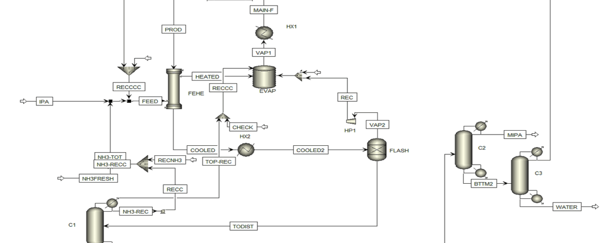
In the process of producing IPA and ammonia, fresh feed enters as a liquid at a rate of 100 lb-mol/h and combines with two liquid recycle streams: ammonia recycle D1 and DIPA recycle D3. Two vapor recycle streams are also added; one from a flash tank and other from the vapor vent in the reboiler of the first column. The first stream consists of hydrogen and ammonia and is compressed, while vent stream is compressed to remove hydrogen. Liquid enters a feed-product heat exchanger (FEHE) that recovers 4.94 × 10⁶ Btu/h of energy. The preheated stream is then transferred to a vaporizer that generates vapor at a temperature of 308 degrees Fahrenheit, which is directed to another heat exchanger to adjust temperature and pressure of the reactor.
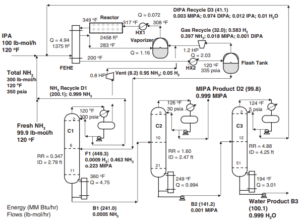
The conversion of isopropanol (IPA) increases with an increase in the inlet temperature. Aspen Flowsheet design characteristic has been used to adjust the output molar flow rate of IPA from reactor to 0.5 lb-mol/hour (with a fresh feed flow rate of 100 lb-mol/hour). Vapor pressure used in the vaporizer depends on the composition:
high ammonia recycle uses low-pressure vapor, while low ammonia recycle requires high-pressure vapor because the high concentration of DIPA raises the vaporizer’s temperature. The reactor is a gas-phase tubular reactor with a length-to-diameter ratio of 10, and the Aspen Flowsheet design characteristic has been utilized to size the reactor to maintain a residence time of 6 minutes. The reactor contains a solid catalyst, and the reaction is exothermic.
Ammonia Recovery Column C1
This column has 12 stages, with the feed entering at stage 6. This feed stage is optimal for reducing the heat input to the vaporizer. The operating pressure of this column is 300 pounds per square inch. A partial condenser is used with a small discharge flow from the bottom reboiler to maintain the condenser temperature at 120 degrees Fahrenheit.
MIPA Product Column C2
This column has 22 stages and is fed at stage 10.
Two design specifications for this column are:
1) DIPA impurity in the overhead stream is 0.05% molar
2) MIPA impurity in the bottom stream is 0.1% molar
In addition to the mentioned specifications, energy consumption, reflux ratio, and column diameter must be within an appropriate range.
DIPA Recovery Column C3
– The column C3 has 52 stages and the feed enters at stage 12.
– Design specifications:
1) Water impurity in the overhead stream is 1% molar
2) DIPA impurity in the bottom stream is 0.1% molar
As mentioned for C2, energy consumption, reflux ratio, and column diameter must also be within an appropriate range for this column.
– The column operates under vacuum to maximize the relative volatility.
– Theoretical plates are assumed, and capital costs for the yield of the plates have not been adjusted.
Economic Optimization
1. Optimal Economic Design: The process involves a tubular reactor and three distillation columns. There are two recovery streams: gas and liquid. The goal of the optimal design is to strike a balance between reactor costs and separation costs.
2. Balance Between Two Recovery Streams: One of the interesting experiences of this process is the existence of two recovery streams, both of which are distillation products from different columns. Increasing ammonia recovery leads to a reduction in DIPA recovery. Therefore, the optimal design must balance these two effects.
3. Optimization Design Variables: The most significant optimization variable is the ammonia-to-isopropanol input ratio. This ratio is selected with the objective of minimizing the Total Annual Cost (TAC), which is a combination of capital investment costs and energy costs.
4. Optimization Results: The optimal ammonia-to-isopropanol ratio is 3, resulting in a total annual cost of $1.38 million. This includes $1.94 million in capital investment costs and $0.734 million in energy costs.
5. Sensitivity Analysis: Sensitivity analyses indicate that increasing ammonia recovery leads to higher energy costs for the ammonia column and lower costs for the DIPA recovery column. Therefore, the optimal design must balance these conflicting impacts.
Overall Control of The Plant
Dynamic Model Measurement:
– Pumps and control valves are integrated into the flow diagram, and pressure-based simulation is employed to analyze control performance.
– Design conditions include a pressure drop of approximately 50 psi across the control valves, and pump heads are selected accordingly.
– Return drums and other equipment are measured for 5 minutes at a 50% level.
– The volumes of heat exchangers are calculated based on heat transfer area and pipe dimensions.
Control Structures for Distillation Columns:
– Distillation columns typically utilize single-loop control.
– The heat input to the reboiler is adjusted based on the temperature of a tray, maintaining the reflux ratio (R/F).
– Steady-state results are generated using Aspen Plus, and variations in reflux flow rates are recorded.
– For columns C1 and C2, single-loop control is effective, while column C3 requires double-loop control due to significant variations in R/F and reflux ratio (RR).
– To determine the tray location that should be controlled, temperature profiles in the column can be examined to identify the area where temperature variations occur significantly.
In addition to the above, overall control includes the following:
1. The flow of fresh IPA is controlled as an input control.
2. The total ammonia ratio (fresh and recycled feed) is adjusted to the IPA flow.
3. The reboiler level is controlled with heat input.
4. The reactor inlet temperature is controlled via heat input to HX1.
5. The outlet temperature from condenser HX2 is controlled through heat removal.
6. Pressures in all columns are controlled by heat removal from the condenser.
7. Base levels in all columns are controlled by outlet flow rates.
8. Return drum levels in all columns are managed by distillate outlet flow rates.
9. Reflux rates are correlated with the feed rates to the columns.
Control Systems in Chemical Processes
The following outlines the control systems in chemical processes, focusing on key points:
1. Liquid Level Control:
All controllers are set to a proportional gain (Kc) of 2, except for the level control in the return tank of column C3.
2. Temperature Control:
The temperature control loops have a dead time of 1 minute and are optimized using feedback tests and the Tyreus-Luyben tuning rules.
3. Flow Rate Increase Results:
A 5% increase in the setpoint of the IPA flow controller leads to stable control; however, the average temperature temporarily decreases by more than 10 degrees Celsius, and ammonia impurity levels increase.
4. Results of Adjustments:
Adjustments in the ratio of QR1/F1 have significantly reduced the peaks in temperature deviations and ammonia impurity levels.
These points clearly outline the challenges and improvement solutions in the control of chemical columns.
Impact of a 20% Increase in IPA Feed Flow Rate on Chemical Processes:
An increase in the IPA feed flow rate leads to transient deviations; however, stable control contributes to maintaining the column specifications.
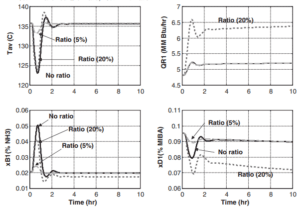
If the total ammonia flow rate reaches 120 lb-mol/h, the stoichiometry of the reaction is maintained. The feed flow rate, as well as the distillate and bottoms flow rates in column C1, also increase, and temperature control establishes new settings. In column C2, the feed flow rate gradually increases, and the purity of the MIPA product is maintained, but temporary impurities occur in the B2 bottoms.
Recent analyses indicate that using the reflux ratio (RR) instead of the reflux-to-feed ratio (R/F) is ineffective for separation in C3, with RR results being significantly worse than R/F. Specifically, the recycled DIPA flow decreases during a 10-hour simulation. Controlling the DIPA composition in the bottoms with high purity is challenging; therefore, control is selected at the middle tray, which has a higher DIPA composition.
Process Description
Raw Material Inputs:
The main reactants are introduced into the system through inlet lines. These materials typically include propylene and ammonia.
Chemical Reaction:
In one or more reactors, propylene and ammonia react together to produce mono-isopropyl amine. These reactors may operate using catalysts and under specific temperature and pressure conditions.
Separation and Purification:
The product output from the reactor includes mono-isopropyl amine and by-products. Distillation columns are used to separate and purify mono-isopropyl amine. By-products and excess materials are separated through outlet lines.
Recovery and Recycling:
Certain sections of the system may be designed for the recovery and recycling of unused reactants or usable by-products.
Control and Optimization:
Control instruments such as valves, sensors, and controllers are installed to precisely adjust temperature, pressure, and flow rates in the system for process optimization.
Process Simulation:
In the simulation of the mono-isopropyl amine production process, complex stages are meticulously designed and modeled.
Reactor Design:
– Reactor Type: Fixed-bed, fluidized-bed, or tubular reactors may be utilized.
– Reaction Conditions: Temperature and pressure are carefully controlled to maximize reaction efficiency.
– Catalyst: Specific catalysts may be employed to enhance reaction rates and improve yield.
Flow Modeling:
– Input and Output Flows: Input and output streams are accurately simulated using chemical models and mass transfer principles.
– Software Utilization: Software is utilized to simulate the distribution of temperature and pressure throughout the system.
Separation and Purification Systems:
– Distillation: Distillation columns are typically employed for the separation of products.
– Adsorption and Desorption: Adsorption processes may be utilized for the removal of impurities and the recovery of materials.
Process Control:
– Simulation Software: Simulation software enables engineers to test and implement various control strategies.
– Closed-Loop Control: Closed-loop control is used to automatically adjust process conditions and respond to environmental changes.
Process Optimization:
– Sensitivity Analysis: Engineers use simulations for sensitivity analysis and optimization of key parameters.
– Objectives: The aim is to reduce costs, increase yields, and minimize environmental impacts.
These simulations provide engineers with a comprehensive understanding of the production process, allowing for more informed decisions regarding the design and optimal operation of the system.
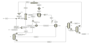
The engineering, design, and simulation of the MIPA process in Aspen Plus encompass critical stages, including conceptual design, process simulation, and optimization of operational parameters. Aspen Plus, with its advanced capabilities for simulating complex processes, serves as a powerful tool for chemical engineers in the analysis and design of processes. This software facilitates high-precision modeling of chemical processes, sensitivity analyses, and the optimization of operational conditions.
In such projects, it is crucial that all design phases—such as the selection of raw materials, reaction conditions, required equipment, and control systems—are meticulously examined and simulated. These processes demand a deep understanding of chemical and engineering theories, as well as experience in utilizing simulation tools.
Anil Pars Process Company, equipped with a specialized and experienced team in the field of chemical engineering and proficient in advanced software like Aspen Plus, is capable of executing complex projects such as the design and simulation of the MIPA process. By leveraging cutting-edge technologies and adhering to international standards, the company can provide precise and cost-effective engineering solutions for the optimization of industrial processes.
Technical Knowledge and Simulation of MIPA Process (Aspen Plus)
In this project, the MIPA process has been simulated using Aspen Plus. The project includes comprehensive training materials.
