Introduction
Pyrolysis gasoline is a byproduct of the olefin unit that is unstable due to the presence of alkenes, styrenes, aromatics, and other compounds. Depending on the processing conditions, these materials can polymerize in subsequent operations. Additionally, the sulfur compounds found in pyrolysis gasoline act as catalyst poisons. The hydrogenation process is a refining process that employs specific and selective catalysts along with hydrogen gas to separate impurities and saturate unsaturated hydrocarbons.
Impurities such as organic sulfur, organic oxygen, and nitrogen must be removed, and unsaturated hydrocarbons need to be sufficiently saturated. The hydrogenation process should be performed on any hydrocarbon mixture containing olefins and diolefins, especially those containing sulfur, nitrogen, and oxygen pollutants, if these mixtures are to be sent to catalytic reforming processes. Furthermore, end consumers may require “high-octane gasoline” or “clean aromatic feedstock” for aromatics plants, which might utilize naphtha as feedstock. In this project, the simulations were conducted according to the industrial PFDs.
Pyrolysis Gasoline Hydrogenation Unit
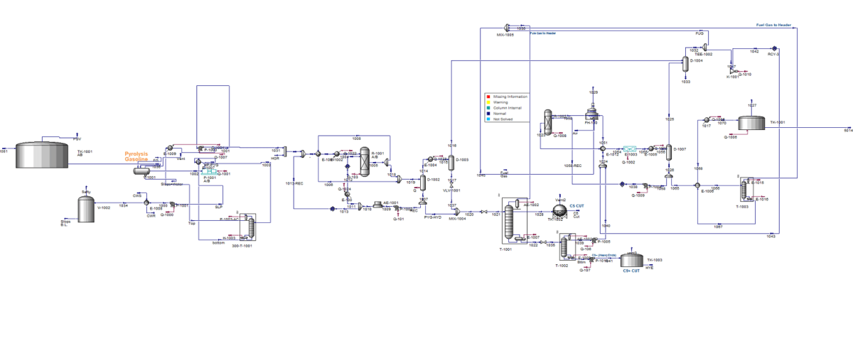
This unit hydrogenates the pyrolysis gasoline produced in the olefin unit in two stages. The annual capacity of the unit is 270,000 tons of pyrolysis gasoline. In the first stage, unstable compounds like diolefins, alkyl aromatics, and some olefins are hydrogenated using a fixed-bed reactor to stabilize the pyrolysis gasoline. A palladium catalyst (LD-365) is employed in this stage. In the second stage, two different catalysts are used in two fixed beds for the recovery of aromatics and the desulfurization of olefins. Liquid coolant injection between beds is used to control the temperature in both stages.
Process Description
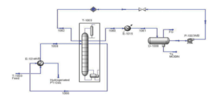
To simulate the distillation column 1003, the input-output loop method along with the modified Peng-Robinson equation of state was utilized in Aspen HYSYS software. This method, which is mainly specific to this software, provides extensive flexibility for designing, sizing, optimizing, and connecting ancillary equipment. The process flow diagram of the secondary stabilization column of the pyrolysis unit is shown in the figure below. The following assumptions were considered for the simulation:
– Distillation column: The condenser unit was simulated externally and then connected to the distillation column.
– Air cooler: Modeled as a simple cooler, with the operating conditions of the outlet streams determined based on specified operational data.
– Heat exchangers: Flow-flow heat exchangers, such as heat exchanger 1014, were simulated as endpoints suitable for steady-state simulation.

Conclusion
The hydrogenation process is an example of a complex industrial facility that holds particular importance in design and construction. This process is used to enhance hydrocarbon feeds containing impurities such as sulfur, nitrogen, and unsaturated hydrocarbon compounds. In oil and gas refineries, valuable products derived from steam cracking cuts may be contaminated by these pollutants, making their removal in later stages of the process essential. Moreover, hydrogenation is employed to increase the octane number of gasoline and diesel fuels.
Simulation of Pyrolysis Gasoline Hydrogenation
In this project, the hydrogenation of pyrolysis gasoline has been simulated using Aspen Hysys version 14.


