Introduction
Ethyl acetate is recognized as a key organic solvent, widely used across various industries due to its low toxicity, competitive pricing, and favorable solvent properties. Currently, the global production capacity is estimated to be around 3 million tons annually, which is likely to increase due to rising consumption of ethyl acetate in the forthcoming years. Therefore, enhancing ethyl acetate production and designing new units using more efficient processes compared to conventional methods is essential.
The direct esterification process remains the most common method for producing ethyl acetate, where ethanol and acetic acid react in the presence of an acidic catalyst. Other chemical pathways for producing ethyl acetate on an industrial scale involve acetylation of ethylene or dehydration of ethanol; however, these methods are often economically unfeasible and pose safety risks.
Process Description
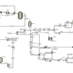
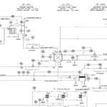
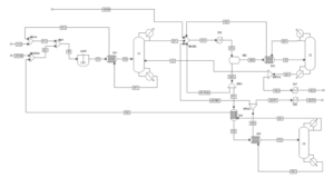
The diagram presented shows a process flow diagram of an ethyl acetate production unit designed using ASPEN Plus simulation software. This diagram generally displays the material flow and main equipment of the unit. Given the limited information provided, the following analysis will be based on general chemical engineering concepts and the processes involved in ethyl acetate production.
Main Components of the Unit and their Functions
– Mixers (MIXA and MIXB): These devices facilitate the production of a homogeneous feed stream for subsequent process stages by combining raw materials.
– Pumps (P1 and P2): Pumps increase the pressure of the fluid, aiding its transport to various sections of the unit.
– Heat Exchanger (E1): This equipment is used for heating or cooling fluids; in this case, it is likely used to heat the input mixture for the reaction.
– Reactor (R-1001): The core of the unit where the ethyl acetate production reaction takes place, typically between acetic acid and ethanol in the presence of a catalyst.
– Separator Tank (S1): This tank is used to separate the reaction products from each other. Usually, the main product (ethyl acetate) exits as vapor from the top of the tank, while byproducts and unreacted materials exit as liquid from the bottom.
– Heat Exchanger (EX1): This exchanger is likely employed for condensing ethyl acetate vapors.
– Distillation Column (C1-RD): This column is used for purifying the final product (ethyl acetate). In this column, ethyl acetate is separated from other compounds and exits as the final product from the top of the column.
Other equipment such as valves, pipes, and instrumentation are also depicted in this diagram to control the flow of materials and process parameters.
In the production of ethyl acetate, four different processes have been examined, with various options compared based on energy consumption, capital costs, operating costs, etc. The first process is the conventional method of ethyl acetate production through the esterification of acetic acid in the presence of ethanol. In the fourth process, a supplementary chemical reaction is considered as a chemical modification of RD.
Conventional Ethyl Acetate Production Process (Direct Esterification)
Typically, the esterification reaction of acetic acid with ethanol is utilized to produce ethyl acetate. A process consisting of a continuous stirred tank reactor (CSTR) and several separation columns has been reported as the most widespread commercial method for ethyl acetate production. At least three distillation columns are required to separate the effluent from the CSTR. This process has high energy consumption and typically results in large equipment due to distillation boundaries and return flows.
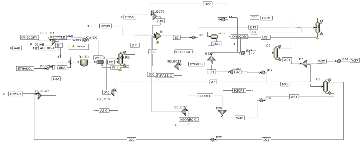
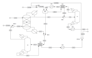
A schematic of the process is shown below.
The esterification reaction occurs in a CSTR, followed by an azeotropic distillation column and two conventional columns. Raw material flows (AA0 and ETOH0) are mixed with return flows and directed to the adiabatic CSTR (R1). Since the conversion in the esterification reaction is slightly over 60%, the reaction mixture contains four components (acetic acid, ethanol, water, and ethyl acetate).
The product stream from the reactor (P1) is then heated in heat exchanger EX1. This mixture is separated in the azeotropic distillation column C1, which has two feed streams. The bottom product (W11) contains unreacted acetic acid and water, which is recycled to the CSTR. The azeotropic mixture of water, ethanol, and ethyl acetate is obtained from the top of the column (D11). Pure water is added to overcome the distillation boundary, and the mixture (D12) is cooled in heat exchanger EX2.
The water phase (H2OL) and organic phase (ORG) are separated in decanter DEC. The organic phase primarily contains ethyl acetate. Pure ethyl acetate is separated in distillation column C2 as the bottom product (W21). A portion of the pure ethyl acetate stream is returned as an azeotropic enhancer (AZ) to column C1. The final product (W22) is cooled in heat exchanger EX7. The top stream from distillation column C2 (D21), containing a ternary mixture of water, ethanol, and ethyl acetate, is cooled in heat exchanger EX3 and returned to the decanter.
Enhancement of the Conventional Ethyl Acetate Production Process using Reactive Distillation
The improvement of the previous conventional process can be achieved by integrating reaction and separation through the reactive distillation method. Several RD plants for ethyl acetate production are operating worldwide with an annual capacity of 20,000 tons. Since RD is a multipurpose reactor concept that combines reaction and separation mechanisms in one unit, it leads to benefits such as reduced equipment count, unit size, improved process efficiency, and consequently, enhanced process economics. The columns CSTR, EX1, and C1 are grouped into one RD column, thus the reactor (CSTR) and two heat exchangers are eliminated compared to the previous process. A schematic of the ethyl acetate production process utilizing reactive distillation is presented below.
The reactive distillation column has two feed streams: acetic acid feed (AA0) and ethanol feed (ETOH). In this process, all the acetic acid is consumed in the RD. Therefore, the top stream of the RD column (D11) contains an almost azeotropic mixture of water, ethyl acetate, and ethanol, while the bottom product (W11) contains a mixture of water and ethanol. The composition of the top stream from the reactive distillation column is such that the stream (D11) can be directly separated. Distillation column C1 is set up to purify ethyl acetate. The bottom product from column C1 (W21) contains pure ethyl acetate, which is cooled in heat exchanger EX5. The ternary azeotrope of water, ethyl acetate, and ethanol exists in the distillate column C1 (D21).
Thus, columns C1 and C2 operate similarly in the original process. The distillate stream D21 is cooled in heat exchangers EX1 and EX2 and enters the decanter DEC for ethyl acetate extraction. Pure water is fed into the DEC, and the organic phase (ORG1) and aqueous phase (H2OL) are separated. The organic phase (ORG1) is preheated in EX1 and mixed with (D11). The aqueous phase (H2OL), which contains some ethanol and ethyl acetate, is mixed with the bottom product stream of the RD column (W11) and heated in heat exchanger EX3.
A distillation column C2 is used for water recovery. All ethanol and ethyl acetate are obtained in the overhead from column C2 (D31), which is returned to the RD column. Pure water is separated in the bottom product of C2 (W31), cooled in EX3 and EX4. The molar ratio of water to the ethyl acetate product (W22) is separated as the final product (H2OP), and the remaining water is returned to the decanter (H2OREC).
Ethyl Acetate Production Process with Reactive Distillation and Stripper
The second state processed using reactive distillation was improved compared to the conventional ethyl acetate production process; however, there is still room for further optimization, such as reducing the large flow of return stream to the decanter or decreasing the equipment count. Since the reaction in the RD process overcomes distillation boundaries, the decanter can be eliminated, and recovery of the azeotropic mixture can be accomplished via distillation.
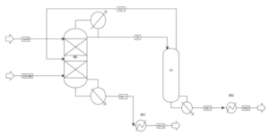
Moreover, the ethanol-water mixture from the RD column (W11) can be efficiently separated into pure water (high boiling point) and ethanol-water mixture at high ethanol concentrations. Therefore, the second state process was further improved: column C2 was integrated with the bottom of the RD. The decanter and heat exchangers EX1 and EX2 were eliminated, and the overheated vapors from C1 were fed back into the RD column (as shown below). Thus, the process design includes two columns and three less heat exchangers compared to the previously indicated process.
This process consists of two columns: the RD reactive distillation column and column C1.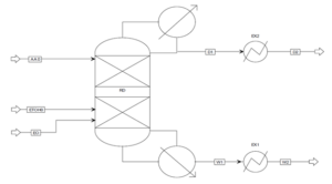
Ethyl Acetate Production Process with Reactive Distillation and Auxiliary Reaction
The ethyl acetate production process using reactive distillation with a stripper has significantly reduced the equipment count compared to the configurations of the conventional process and the reactive distillation process. Furthermore, integration and further enhancements to the process are limited by the presence of water. The formation of a ternary azeotrope involving water, ethyl acetate, and ethanol necessitates at least two columns for its separation. Additionally, the conversion of the esterification reaction is suppressed with increasing product concentrations. Therefore, efforts to improve the process and reduce the equipment count aim at eliminating water as a byproduct. Water can be consumed through an auxiliary chemical reaction. If the hydration of ethylene oxide (EO) is employed as the auxiliary chemical reaction, the ternary azeotrope is eliminated, resulting in the formation of another valuable product known as monoethylene glycol (MEG). This idea is derived from the industrial production of glycols.
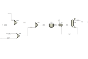
The final process consists of only one column (as illustrated below) with three feed streams: crude acetic acid (AA0) enters the top section, crude ethanol (ETOH0) enters the middle, and pure ethylene oxide (EO) enters the bottom section of the RD column. Because this setup is entirely integrated, there are only two product streams: the distillate (D1) containing pure ethyl acetate and the bottom product (W1) containing monoethylene glycol. Both product streams are cooled sequentially in heat exchangers EX1 and EX2 (as illustrated below).
Comparison of Different Ethyl Acetate Production Processes
In this section, the four processes mentioned above are compared regarding the number of equipment and energy consumption, utility costs, installation costs, capital costs, operating costs, and product sales.
Table 1 compares the energy costs required and the number of equipment for each of the four processes. As seen, each modification stage reduces the main equipment count and heat exchangers such that only one column and two exchangers are needed in the final process. The energy required for the last process is significantly lower than that of the conventional ethyl acetate production process.
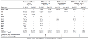

Table 2 compares the utility costs required for each of the above processes. As anticipated, the utility costs for the reactive distillation process utilizing the auxiliary reaction are lower than all other processes, while the conventional ethyl acetate production process has the highest costs.
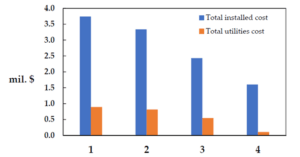
The following figure compares the installation costs and utility expenses of each process. This process also shows the lowest utility costs, as previously mentioned. Unsurprisingly, the conventional ethyl acetate production process fares the worst compared to the other processes.
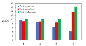
The last figure compares the capital, operational, and product sales costs for each of the processes. As evident, in the process using reactive distillation with an auxiliary reaction, in addition to the targeted product, ethyl acetate, another valuable substance, MEG, is also produced, resulting in the highest sales revenue for this process. Conversely, this process, having the least equipment count, inherently entails the lowest capital costs. The other three processes have similar revenue conditions but differ in capital investment costs.
Conclusion
Ethyl acetate is an organic solvent with widespread applications in various industries, including pharmaceuticals, coatings, and adhesive production. Due to its specific physical and chemical properties, including a low boiling point, high solubility, and chemical inertness, it is used in numerous industrial processes. The design and simulation of industrial units using powerful software like ASPEN Plus help engineers optimize production processes and reduce operational costs. This analysis examined the ethyl acetate production unit with a capacity of 2,400 tons per year, simulated using ASPEN Plus.
In this project, the EDR simulation was also performed.
Simulation of Ethyl Acetate Production Unit with a Capacity of 2400 Tons Per Year (300 kg/h)
In this project, the ethyl acetate production unit with a capacity of 2,400 tons per year (300 kg/h) was simulated in ASPEN Plus software.
