Introduction
Disposing of waste gases in various industries, especially oil industries, has been common for a long time. These gases pollute the atmosphere and are dangerous for humans, animals and plants. Also, some of the gases sent to the flare have a significant economic value that cannot be ignored easily.
One of the places that wastes a lot of capital and energy in refineries is the flare system. It has been tried in this project in order to minimize the gases directed to the flare, the solutions that have been presented so far. should be collected and proposed so that taking into account the current conditions of Shazand Arak refinery, the best proposal for incineration in that refinery can be presented.
Flare Gas
Flare gas contains many compounds, most of which are methane and ethane. Gas flaring has several reasons:
1- Unburned process gas
2- Excess gas that cannot be processed
3- Vapors and gases above the tanks
4- Exhaust gases from the units during shutdown or pressure reduction
5- Exhaust gases during repairs and maintenance
6- Exhaust gases when starting up process units
7- Burning oil and gas wells to clean the wells
8- Fuel gases in operating units. The highest amount of environmental pollution is created in the oil-rich areas of the south and central oil.
Different Methods of Flare Gas Recovery
Injection Into The Well
One of the common ways to collect acid and sour gases is to increase the pressure and inject them into the reservoir to increase the productivity of the wells. For this purpose, the flare gases are directed to the compressors after being collected and passing through the dripper. Choosing the type and arrangement of compressors is one of the most important parts of this plan. After compression and increasing the pressure based on the amount of pressure required for injection into the well, the gas enters the well through the pipeline.
Reuse as Feed or Fuel
According to the composition of flare gas, if the percentage composition of these gases is similar to the feed of some refinery units, it can be used in the input feed of some units or as fuel. This work has been done in Ilam and Tabriz gas refineries.
A flare gas recovery system recovers the gas before it reaches combustion (after exiting the drip trap). It collects and condenses the combustion from the main pipe and cools it for reuse in the fuel gas system of the refinery or as feed to other units. The waste gas recovery system has other advantages such as reducing the visible flame in the flare tower and reducing the noise caused by burning gases in the flare tower.
Gas Injection System Into The Ground to Bury it
If the amount of pollutants such as H2S and CO2 is very high. Actually, sweetening and purifying this gas is not cost-effective and it is recommended to inject these types of gases at a great depth from the ground and practically leave them out of the cycle. Although, by increasing the injection depth, more pressure is required for injection, which in turn increases the operation cost.
Drained oil and gas tanks are also considered a suitable option for disposal of acid gases. Because they have proven their ability to preserve hydrocarbons; But it is not an easy task to find this type of tanks in the vicinity of the acid gas collection site.
The South Pars gas field is the largest gas field in the world, which has significant amounts of CO2 and H2S gases, and this option can be an effective solution to this problem.
Simultaneous Production of Electricity and Heat Through Gases Sent to The Flare
The simultaneous production of electricity and heat through gases sent to the flare has the greatest effect in saving gas consumption, compatibility with the environment and reducing energy losses. If there is no request for generated electricity. By returning these gases to the process and producing steam by exhaust gases from gas turbines, gas waste can be avoided.
These power plants are made from a combination of steam and gas turbines, and depending on the type of turbines, there are several types of heat recovery boilers and recovery devices. The use of microturbines increases productivity and reduces pollution, and since they are light in weight and portable. They are very suitable for use in drilling areas and platforms. Microturbines have the ability to work with different fuels, including sour gas.
System Description
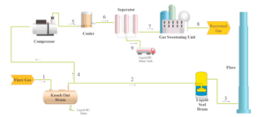
A typical burner gas recovery system with a compressor compression system is shown in the figure below. In the normal operation of the power plant, most of the flare gas flow enters the recovery system (flow 4). And a low mass flow stream is sent to the flare to keep the flare system in standby mode (stream 2).
A liquid seal drum is used to maintain positive pressure in the system and prevent air flow into the recovery unit. The most important part of the recovery system is the compression and separation of condensate from gas. Liquid ring compressors are commonly used for the compression process because of their ability to provide nearly constant temperature conditions for the compressed gas to contact the cooling fluid. The compressor exhaust gas is then directed to the separator (stream 6) after cooling in the cooler (when the liquid ring compressor is not in use) (stream 5).
Then the output gas from the separator is directed to the gas sweetening units to remove acid gases (flow 7). The gas output from the sweetening units is actually the recycled gas that can be used in different ways (flow 8). The hydrocarbon liquid output from the separator can be used as fuel or feed for one of the refinery units (stream 9), depending on its composition.
Description of Gas Sweetening Process
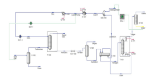
To remove H2S and CO2 from flare gas mixtures, simulation of the sweetening unit by amine solvent was carried out in Aspen Hysys software and is presented in the figure below. Since the sweetening process is affected by the flow conditions of the ejector system outlet, especially its mass. The flow rate, which depends on the arrangement of the ejector system, the sweetening process is analyzed technically and economically. A closed thermodynamic model of amine has been used to simulate the process.
Conclusion
The compression process in flare gas recovery, which is usually done by compressors, is the most expensive. In this project, the use of an integrated gas-gas ejector system instead of a compressor is proposed and it has been investigated from a technical and economic point of view. Therefore, modeling of the flare gas recovery process, including the gas sweetening unit, is performed for both compressor and ejector systems. Different arrangements of integrated ejector system in the form of multi-stage ejectors (series) in parallel branches were also investigated.
To find the geometry of the ejectors, it was developed to simulate the integrated ejector system in SPANHISIS. The results of the economic analysis showed that the compression method with the arrangement of three parallel branches (including a three-stage ejector in each branch) is the most suitable solution in the recovery of flare gas of a typical oil refinery plant. As well as the accepted payback period of 2 years and the recovery of approximately 90% of the flare gas volume during normal operation.
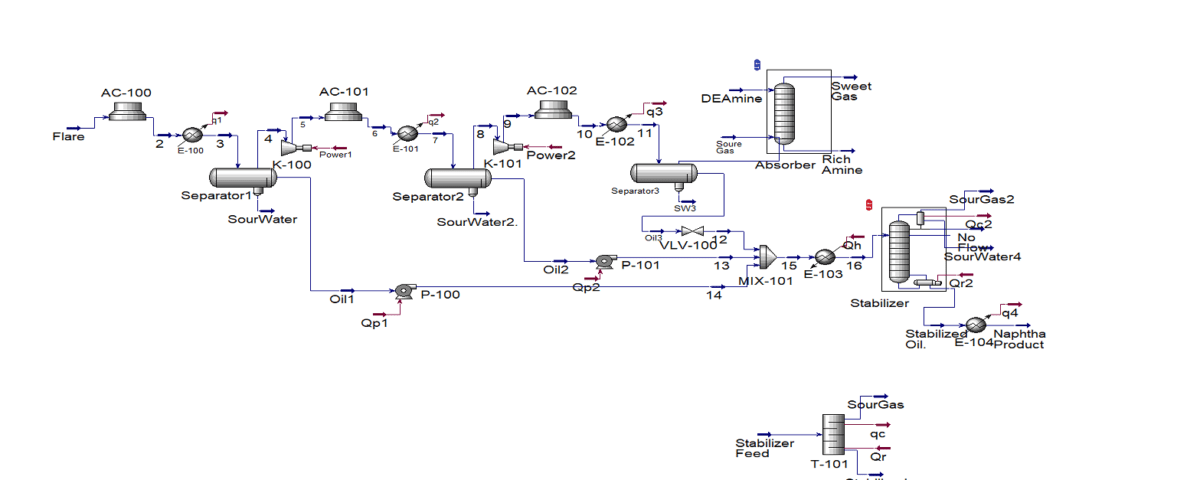
Recovery of Flare Gases SHAZAND ARAK Pet. CO.
In this project, the process of optimizing the recovery of Shazand Arak petrochemical flare gases is simulated in Aspen Hysys version 14 software.
