Introduction
Phosphoric acid is considered a strategic material in the basic chemical industries due to its applications in various sectors and the lack of suitable alternatives. This substance is generally produced in different industries with diverse applications through two main methods: the wet process, which involves the acidulation of apatite with sulfuric acid, and the thermal process, which involves the combustion of phosphorus.
Wet Process

Thermal Process
![]()
Methods of Producing Phosphoric Acid
Thermal Method
The main process for producing thermal phosphoric acid involves burning phosphorus and then hydrating it. This process can be divided into single-stage and two-stage methods. In industry, the two-stage electric-thermal method is used. In this method, the apatite ore is crushed to a size of one millimeter and then completely dried. Inside the dryer, the ore is exposed to combustion gases from the furnace at temperatures between 450 to 600 degrees Celsius. It is then mixed with coke and silica and fed into the electric furnace.
![]()
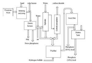
The furnace used in this method is of the electric arc type, and as a result of regeneration, white phosphorus comes out of the furnace in the form of gases with some dust. After passing through the condenser, the phosphorus vapor is converted into solid phosphorus, which is collected at the bottom of the tower in the receiving section. Solid phosphorus, along with some sludge and water. is sent to the purification section. where it is washed with steam and separated from sludge based on density differences, settling at the bottom of the purification tank. The white phosphorus produced at this stage is then pressurized and mixed with air before being sprayed into the upper combustion section.

The product from the furnaces is transferred directly to the hydration tower, where phosphoric acid is absorbed in the phosphoric acid recovery process. Alternatively, phosphorus burns in dry air. Phosphorus pentoxide is obtained as a solid white powder, which is then separately used for combining with water to produce phosphoric acid.
![]()
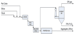
IHP Method
IHP method, which stands for Improved Hard Process. is a process through which phosphoric acid of technical grade can be obtained by using a rotary Furnace and producing agglomerated granules from phosphate ore and coal. This process can serve as a suitable alternative to wet methods and electric arc furnaces in the production of phosphoric acid. IHP process helps avoid costs associated with establishing industrial units using wet methods, which relate to washing, separating fines from the ore, and storing them in waste storage tanks.
In comparison to the Furnace process. IHP process requires silica as an additional secondary raw material to prevent the melting of the charge inside the Furnace; this amount must be greater than the mineral content. Additionally, low-grade phosphate ores mixed with a higher amount of silica can also be utilized for phosphoric acid production using IHP method. Currently, there are many low-grade phosphate resources worldwide that are not economically viable for processing through wet methods or electric arc furnaces, but utilizing the IHP method can make them economically feasible.
Wet Method
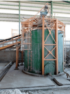
for producing phosphoric acid, sulfuric acid is typically used to react with phosphate ore. This reaction takes place in a tank called the attack tank. In one common technology, the attack tank is a concrete chamber lined with elastic coating and graphite bricks to prevent corrosion. The internal walls divide the attack tank into several smaller compartments through which the pulp resulting from the reaction flows.
To ensure maximum uniformity in the reaction flow and to prevent gypsum precipitation, each compartment of the attack tank is equipped with a mixer. Apatite added to the attack tank can be sent to the reaction chamber either in a dry form or as pulp. Sulfuric acid, the pulp of the ore, and diluted phosphoric acid returned from the filter are introduced into the second and third compartments of the attack tank through mixing pipes. The reaction between sulfuric acid and apatite produces phosphoric acid and gypsum, which is an exothermic reaction. Therefore, if the heat released is not removed, the temperature of the pulp in the attack tank will increase.
The Various Methods for Producing Phosphoric Acid Include:
– Processes in which dihydrate calcium sulfate, referred to as dihydrate, is formed and separated. If it is hemihydrate, it is called hemihydrate, which can be produced as an intermediate or final product.
– HDH (Hemi-Dihydrate Process): Materials in the reactor react under hemihydrate conditions. In the next stage, product passes through an intermediate filter to convert hemihydrate crystals into dihydrate crystals.
– HDHH (Hemi-Dihydrate to Dihydrate Process): In this process, Materials in the reactor react under dihydrate conditions. After undergoing a filtration step, dihydrate crystals are converted into hemihydrate crystals.
– HRC (Hemi-Dihydrate Conversion): In this process, Materials in the reactor react under hemihydrate conditions, and in the next stage, these crystals are converted into dihydrate crystals without intermediate separation.
Phosphoric Acid Production Process
Reaction Unit
To produce phosphoric acid, sulfuric acid reacts with phosphate rock in a reactor tank. This tank is designed with concrete, rubber lining, and graphite bricks to prevent corrosion, and it is divided into several small chambers where the slurry resulting from the reaction flows. Each chamber is equipped with a stirrer to prevent gypsum precipitation, and the flow rate of the phosphate rock slurry is accurately measured.
Sulfuric acid, the phosphate rock slurry, and diluted phosphoric acid returned from filtration are transferred to the second and third chambers, where the reaction produces phosphoric acid and gypsum. This reaction is exothermic, and if heat is not removed, the temperature of the slurry will increase.
The gypsum crystals produced can be dihydrate or hemihydrate, depending on the temperature. At lower temperatures, dihydrate crystals are stable, while at higher temperatures, hemihydrate crystals prevail. These processes lead to various methods of phosphoric acid production, such as the DH method, HH method, and other combined processes.
Dihydrate Method
To remove the heat released from the reaction between sulfuric acid and rock and to control the temperature, the slurry from the fourth chamber of the attack tank is directed into a flash cooler. Here, it is cooled by evaporation under vacuum conditions and then returned to the first chamber of the attack tank. By controlling the vacuum in the flash cooler, the rate of evaporation and consequently the temperature can be managed.
As described above, the circulation of the slurry in the attack tank flows from the first chamber to the second, third, and fourth chambers, then enters the flash cooler, and returns to the first chamber. In accordance with the incoming flow of sulfuric acid and phosphate slurry, a portion of the slurry overflows from the fourth chamber of the attack tank into the digestion tank, from where it is transferred to the filtration unit for the separation of phosphoric acid and gypsum.
Objective of The Reaction Unit
The objective of the reaction unit is to create conditions that allow the complete effect of sulfuric acid on the rock, leading to the formation and adequate growth of gypsum crystals. This will ensure that the gypsum can be easily separated from phosphoric acid in the filtration unit. To achieve this, the following parameters must be controlled in the attack tank:
– Ratio of sulfuric acid to incoming phosphate slurry
– Temperature of the chamber
– Free SO3 present in the slurry
– Solid materials present in the slurry
– P2O5 content in the slurry
– Level of the slurry in the attack tank
Filtration Unit
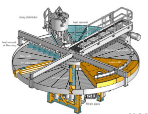
The slurry obtained from the attack tank, after the reaction is completed in the digestion tank, is pumped to the filtration unit. In this unit, the slurry is poured onto filter screens, and through suction created by a vacuum pump, phosphoric acid passes through the screens while gypsum particles remain on them. Filtration can be either belt-type or rotary, depending on the capacity, and the type of filter is selected accordingly.
In this process, the slurry is distributed by an input box over the filter, and phosphoric acid is directed through a pipe to the tank beneath the filter. The remaining gypsum on the screen contains some acid, which, after the filter rotates and the gypsum is washed with water, dissolves the residual acid, converting it into a dilute solution. This solution is returned to the reservoir, and the acid obtained from the second washing is transferred back to the attack tank.
Concentration Unit
The concentration unit is responsible for increasing the concentration of phosphoric acid through the evaporation of water. Since the boiling point of the acid is higher than the tolerance limit of corrosion-resistant materials, this process is carried out under very low pressure.
In the evaporator, the pressure is regulated by a vacuum pump, and water vapor and other gases are released. The evaporated acid returns to the heater, and over time, the concentration of acid in the loop increases.
In this process, a significant portion of the fluorine present in the phosphoric acid is released as gas SiF4 along with water vapor. These vapors are washed in scrubbers and directed in the form of hydrofluosilicic acid to the corresponding tanks, which is always one of the by-products of phosphoric acid production lines.
PFD Stages of The Phosphoric Acid Production Process
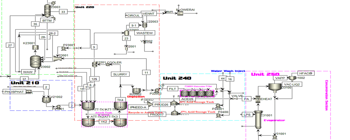
Unit 210
In the first stage, phosphate soil (fluorapatite) is transported to the soil storage by a truck. Then, the soil is loaded into a hopper using a loader. The hopper uses a screen to sieve the soil and separate large clumps. Due to the softness of the apatite soil, it may get stuck in the hopper, so vibrations are created to facilitate the movement of the soil.
Next, the soil is transferred onto a conveyor belt, which is equipped with a permanent magnet that separates any metallic waste present in the soil.
After that, the soil is conveyed into a slurry tank, where it is mixed with water in a specific ratio and agitated by a stirrer inside the tank to create a fluid mixture. The density of this slurry ideally falls within a certain range, which may experience fluctuations depending on operational conditions.
The resulting slurry is sent to the tank by a pump. An important note regarding the pumps in this section is that before the pumps, a device called a strainer is installed, which separates stones and solid debris that could potentially damage the pump.
Unit 220:
The slurry formed in the processing unit is transferred through a pipeline to the first tank of the reaction tower. This tank contains several mixed reactor vessels, with the primary goal of the plant being the production of dilute phosphoric acid. The key reaction, which produces phosphoric acid, takes place in this tank. Alongside the slurry, a flow of dilute acid from the storage tank also enters the first section of the reaction tower. Another important parameter for the reaction is concentrated sulfuric acid. The composition of the raw material varies, which means operational conditions can change with each production cycle. The raw material consists of various elements and substances, including phosphates, fluorine, iron, arsenic, and even traces of uranium. Sulfuric acid is injected into specific vessels within the tank, where the reactions occur.
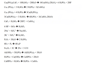
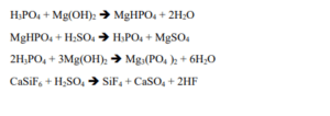
In the process of producing animal feed based on calcium phosphates from phosphoric acid, the acid-containing sludge is returned to the tank. Effective removal of fluorine, arsenic, and heavy metals is essential to meet animal feed standards. The returned acid is filtered and transferred to storage tanks, and water is added if necessary. Materials are pumped from one tank to the flash cooler, where HF gas is separated, and the output slurry is returned to the tank. Key parameters in the tank include temperature and the ratio of sulfuric acid to slurry, which are vital for optimizing reactions and reducing the concentration of pollutants in the final product.
Flash Cooler
In the flash cooler, a vacuum exists that allows for the separation of gas from the slurry liquid. The slurry output from the flash cooler is returned to the first tank, while the gas output is directed to the wash tank and then to the condenser. To maintain an appropriate temperature for vacuum pumps, a condenser is installed next to each pump. Hot water output from the condensers is collected in a tank located below the condenser and is pumped to the concrete tanks for cooling. Hot vapor from the condenser is also cooled with cooling water and sent to the vacuum pump.
The wash water stream, which contains some acid, is directed to the pump filter. The slurry and mixture in the attack tank are transferred to the digestion tank to ensure complete reactions and provide sufficient residence time for the reactants.

Unit 230
In the liquid collection process, diluted phosphoric acid is sent to the storage tank. The remaining slurry, which contains high levels of acid, is transferred to the first washing section, where the materials on the filter are washed with water, resulting in an output liquid with a specific acid concentration. If this concentration is below the desired level, diluted acid is added to the first washing section.
Additionally, the flow is returned to the tank for concentration adjustment and to utilize the produced diluted acid. The output water is transferred to conical-shaped tanks to collect sediments and prevent them from entering the pump. These tanks also ensure that there is always a volume of liquid available before the pump.
Important Points on Arsenic Adsorption and Separation in Phosphoric Acid Production Unit:
Unit 240
Purpose of Returning Acid

Second Washing
Reason for Using a Demister and Condenser
In the final stage of dilute acid production, the stream that is the first output from the filter, containing 26% acid, is introduced as the produced dilute acid into the first dilute storage tank. This tank is equipped with a mixer, and the materials within it are agitated. The dilute acid then overflow flows into the second storage tank. The second storage tank has a rake mechanism that separates the sediments. Additionally, the settled sludge in the second tank is fed into the thickening tank as feed.
Anil Pars Process Industry Company
Anil Pars Process Industry Company is recognized as a leader in the design, simulation, and optimization of industrial processes, providing innovative and up-to-date solutions in this field. With a skilled and experienced team, the company is capable of executing a variety of projects, including P&ID design, process simulation, and optimization of existing systems. Our goal is to enhance efficiency and reduce operational costs for our clients.
One of the special services offered by Anil Pars Process Industry Company is the simulation of phosphoric acid production processes using Aspen Plus software. This software allows us to accurately and in detail model production processes and provide optimal results for our clients. We are committed to delivering the best solutions and high-quality services to help achieve our clients’ industrial goals.
Examples of Projects Completed by Anil Pars Process Industry Company
Simulation of a New Methanol Production Process (Carbon Dioxide Hydrogenation) with Aspen Plus
Simulation of Combined Cycle (CHP, CCHP for Power Generation) with Aspen Plus
Simulation of Carbon Dioxide Separation from Air with Aspen Plus
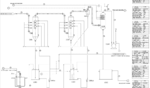
The P&ID design project and simulation of the phosphoric acid production process demonstrate success in providing an accurate and efficient model of this industrial process. Using Aspen Plus software, we were able to conduct a deeper analysis of key parameters and interactions between various components. This simulation not only assisted in optimizing system performance but also enabled the identification and reduction of weaknesses, thereby improving production efficiency.
Basic Engineering and Simulation of The Phosphoric Acid Production Process Using ASPEN PLUS
In this project, the simulation of the phosphoric acid production process was conducted in Aspen Plus, along with the design of the P&ID diagram. The project includes comprehensive training.
