Introduction
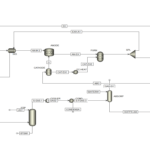
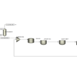
Differential distillation, also known as differential or Rayleigh distillation, is a key method for separating liquid components based on their boiling points. This process is particularly used in the chemical and petroleum industries for producing high-purity products. This project investigates the conceptual design of an industrial differential distillation project to separate naphtha cuts using Aspen Plus software.
Design Fundamentals
The feed entering this unit comprises light naphtha, supplied at a rate of 2000 tons per day, which forms the foundation for the design of the necessary equipment and separation units. The overall process includes two stages of distillation: the first stage involves the initial separation of naphtha cuts, followed by a more precise separation of the 40-65 °C cut using differential distillation techniques.
Process Description
Primary Separation of Cuts
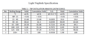
In the first stage, the naphtha feed enters the continuous distillation unit, resulting in the separation of the feed into six cuts:
– Initial Boiling Point Cut: 40 °C
– 40 to 65 °C Cut
– 65 to 100 °C Cut
– 100 to 125 °C Cut
– 125 to 150 °C Cut
– Above 150 °C Cut
Cuts 1, 3, 4, 5, and 6 are sent to storage tanks for sale, while cut 2 (40-65°C) is sent to the differential distillation column for further separation.
Differential Distillation of the 40-65°C Cut
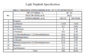
The 40-65°C cut, which contains compounds of various purities, enters the differential distillation column. In this stage, the cuts are divided into the following high-purity products:
– n-Pentane Min purity, wt.% 98
– 2,2-Dimethylbutane Min purity, wt.% 98
– 2,3-Dimethylbutane + 3-Methylpentane Min purity, wt.% 98
– n-Hexane + Methyl cyclopentane Min purity, wt.% 98
– 2,4-Dimethylpentane + Benzene Min purity, wt.% 98
– The rest of the feed from the bottom of the tower
The goal of this process is to achieve high-purity products while maintaining balance among different components during distillation.
Conceptual Design Using Aspen Plus
In this project’s conceptual design, Aspen Plus was used to simulate and analyze the differential distillation process. Specifically, Aspen Plus aided in modeling complex mixtures, predicting equipment performance, and conducting temperature-composition (T-XY) analysis. The T-XY diagram serves as a fundamental tool in analyzing and simulating distillation processes, especially differential distillation. It illustrates the distribution of components in vapor-liquid equilibrium at constant pressure, helping engineers predict and optimize process performance.
T-XY Diagram Analysis in Differential Distillation

– Point B: Represents the initial composition and temperature when the liquid mixture in the still pot begins to boil. The vapor composition produced at this point approaches point C.
– Point C: Indicates the vapor composition at the start of the distillation process, where the generated vapor is richest in the more volatile component. However, this initial vapor amount is insufficient for the entire process, necessitating continuation of distillation.
– Temperature Increase to T2: As temperature increases to T2, the mixture enters the vapor-liquid equilibrium region, changing the liquid phase composition to point D and vapor phase composition to point E. Point E shows that the more volatile component in the vapor has decreased compared to point C.
– Point E: At this point, the vapor composition has become less concentrated in the more volatile component compared to the initial composition at point C. Thus, with the process continuing, the vapor composition changes differentially, becoming richer in the less volatile component.
– Point H: Represents when nearly the last drop of liquid remains. This point is crucial because continued boiling could revert to the initial vapor composition. To prevent obtaining a similar vapor composition to the initial liquid, some liquid is retained in the still pot.
Applications of the T-XY Diagram in Differential Distillation
The T-XY diagram is a key tool for:
– Performance Prediction: Assisting in predicting how compositions change during the process and identifying optimal vapor-liquid composition points.
– Process Optimization: Determining optimal temperature conditions for separating high-purity molecules.
– **Process Management: Aiding in managing the distillation process by adjusting temperature and pressure to achieve desired compositions.
Technical Details of the Differential Distillation Process
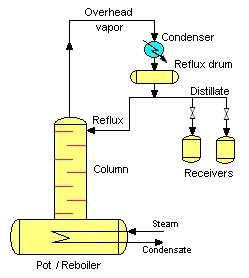
The differential distillation process involves introducing a specific amount of liquid mixture into a vessel called the “still pot.” Steam is introduced through a steam coil, causing the liquid to boil. The steam temperature gradually increases, effectively separating different components based on their boiling points. The generated vapors are sent to a condenser and collected in separate tanks after condensation.
Examination of the 40-65°C Cut Separation Process
After separating the 40-65°C cut from the naphtha, this cut is sent to another differential distillation unit with lower capacity designed to achieve very high purity for various components. Given the high importance of this cut in the pharmaceutical industries, the quality and purity of the product must be controlled meticulously.
Conclusion
The designed project using Aspen Plus has been optimized for separating high-purity molecules from naphtha. This design includes two continuous distillation units: one for the naphtha feed and one for the 40-65 °C cut. This design is not only optimized but is also suitable for use in pharmaceutical industries.
Tables and Data
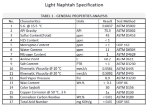
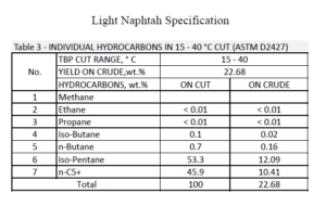
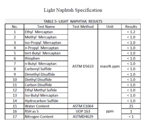
The tables below clearly show the detailed specifications of the feed.
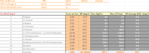
Conceptual Design and Engineering of a MINI REFINERY for Light Naphtha and Gasoline Production Using Aspen Plus
This project investigates the conceptual design of an industrial differential distillation project for separating naphtha cuts using Aspen Plus software.
