Nanofluids and Their Application in Chemical Engineering
مهر ۵, ۱۴۰۳
Gas Sweetening Unit
مهر ۵, ۱۴۰۳Gas Reception Unit
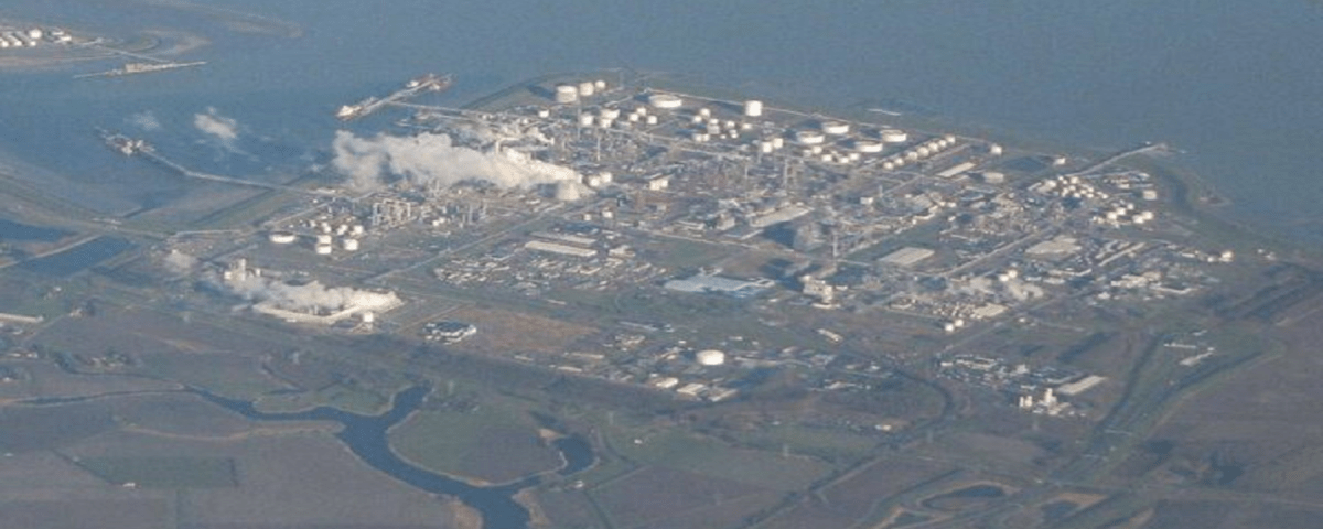
The gas reception unit, also known as the gas reception facilities, is located at the refinery’s entry point. Gas from offshore platforms, in the form of three phases (natural gas, gas condensate, and glycol-water), is transferred through 32-inch Sea lines to the onshore facilities and enters this unit at the refinery entrance.
For each of the southern phases of the country, a Unit 100 is designed, and each unit includes the following sections:
- Manifold Entry and Pig Receiver: This section is designed for receiving pigs from gas transmission lines.
- Gas-Liquid Separation System and Liquid Storage: Known as the Slug Catcher (Finger Type Slug Catcher), it is used to separate gas from liquids and store them.
- Gas Expansion System at the Pressure Control Station: This system is used to control gas pressure in subsequent stages.
- High Integrity Pressure Protection System (HIPPS) and PSV: These systems are installed for protecting the downstream plant equipment.
- High-Pressure Gas and Liquid Separators: Each unit is equipped with two vertical high-pressure separators working in parallel.
- Sour Gas Heaters: These heaters prevent hydrate formation during the winter and in the Packing/Depacking operations.
- Phase Separation of Gas and Liquid: The gas phase is sent to the refining trains (Train) for further refining and purification.
- Sending the Liquid Phase to Unit 103: The liquid phase, which contains glycol, water, and gas condensate, is sent to Unit 103 for condensate separation and stabilization.
- Gas Pressure Reduction and Control: Gas pressure is regulated by the pressure control valve (Pv0037) in the letdown station.
- Receiving Pigs: Pigs sent from the offshore platforms are received onshore by the Pig Receiver.
Pigging Process
As we know, inside the gas transmission lines (Sea lines) from offshore to onshore, there may be objects like rust, sludge, etc., that need to be cleaned. For this purpose, a device called Pig is used. Depending on the application, there are different types of pigs:
- Standard Pig: Used solely for pipe cleaning.
- Magnetic Pig: A magnetic pig used for collecting welding debris and iron objects.
- Intelligent Pig: A smart pig equipped with sensors that records data on corrosion and other pipe conditions while moving through the Sea line, transferring this information to a computer for analysis.
All pigs are designed to match the internal diameter of the pipeline, and multiple pigs can be sent into the pipeline simultaneously. These pigs move toward the shore driven by the gas pressure, typically with a pressure difference of around 12 bars (92 bars behind the pig and 80 bars in front of it). Depending on the type of pig, these pressures may vary.
HIPPS Pressure Control System
The High Integrity Pressure Protection System (HIPPS) is designed to control gas pressure at approximately 82 bars to protect the downstream units (Unit 101). In addition to HIPPS, pressure safety valves (PSVs) are installed in this unit to direct excess gas to the refinery flares in case of a sudden pressure increase.
Pigging Process at the Platform
The pig is loaded into the Pig Launcher at the offshore platform and sent toward the shore. Onshore, in the first section of Unit 100, the pig is safely received by the Pig Receiver following specific procedures. The gas flow is then diverted from the Pig Receiver back to its normal path.
Gas and Liquid Phase Separation
After being received, the two-phase flow (natural gas, condensate, and glycol) moves toward tubular separators known as Finger Type Slug Catchers, where the gas and liquid phases are separated. This separator consists of four sections:
- Gas & Liquid Separation Area: This section is 13 meters long with a 1/20 slope.
- Intermediate Section: 23 meters long with a 1/20 slope.
- Slug Catcher Section: 330 meters long with a 1/100 slope.
- Liquid Bottle Section: The separated liquid phases, including glycol and gas condensate, gather in this section.
The gas phase is separated in the first 13 meters and transferred through vertical pipes (Risers) to the Letdown Station, where gas pressure is reduced from around 79 bars to 68 bars using the pressure control valve Pv0037. The gas is then directed to a separator called HP Separator to remove any carried-over liquids (Carry Over). After passing through a gas heater, the gas temperature rises from approximately 15.5°C to 22.5°C before being sent to the refining trains (Train).
The liquid phases (gas condensate and glycol) flow to the end of the Five Finger section, where the Liquid Bottle separates the glycol-water phase (bottom) from the gas condensate phase (top). Each phase is filtered separately to avoid emulsion formation in the control valve (Control Valve). If not filtered, particles from both phases could stick together and cause issues in Unit 103, particularly during the separation process in the Preflash Drum. After filtering, the phases are recombined and sent to Unit 103.
It is worth mentioning that the glycol line contains three filters and the gas condensate line contains two filters. One filter from each line is always in standby mode, and the filters in service are replaced when the pressure difference (DP) exceeds a certain limit.

