Process Design Simulation Software
مهر ۱۹, ۱۴۰۳
Providing PDP and FEED For New Pet. CO. Projects by APIPCO
آبان ۱۰, ۱۴۰۳Introduction
Process Design Package (PDP) includes a comprehensive set of documentation and technical information. which describes in detail all aspects of designing and implementing a specific industrial process. These documents are very important for engineers, contractor managers and project stakeholders and form a main reference for all activities and decisions related to the project.
Components and Details of The Process Design Package
1. Analysis
Needs analysis is a critical step in process design, which includes the identification and analysis of user needs. This stage can be examined from the following points of view:
– Identification of Beneficiaries: In this step, the people who will be affected by the process should be identified. Beneficiaries can include customers, employees, managers, suppliers and other groups.
– Collecting Information: different methods should be used to collect information.
– Analysis: After collecting information, it is necessary to analyze the data and identify the real and basic needs. In this step, surface needs can be separated from basic needs.
– Definition of Objectives: The objectives of the process design should be determined based on the identified needs. These goals serve as guidelines for the next steps.
2. General Description of The Process
– Purpose and Scope: Descriptions about the general purpose of the design and its specific needs.
– Overall Performance: description of the overall performance of the process and its importance in the industrial system.
– Market Analysis and Needs: examining customer needs and market analysis to determine final products.
3. Process Diagrams
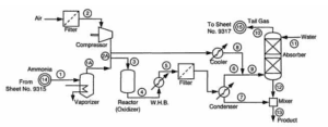
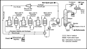
– Process Flow Diagram (PFD): A representation of different process steps, inputs and outputs. This diagram usually includes material and energy flows, key equipment, and relationships between the various steps.
– Control Diagram (P&ID): Contains details of controls and safety systems, such as sensors, valves, and pipelines.
4. Process Modeling
Process modeling deals with designing and drawing process steps and activities. This stage is dedicated to visualization and analysis of existing processes. Important points in this regard are:
– Creating Work Flow Diagrams: these diagrams show the different stages of the process. Using standard symbols (such as BPMN) helps the process to be easily understood.
– Identification of Roles and Responsibilities: modeling helps to specify different roles in the process. These roles include people who have specific tasks and their responsibilities should be defined.
– Analysis of Strengths and Weaknesses: by modeling the process, one can find out its strengths and weaknesses. It is also possible to identify which steps may need to be improved or eliminated.
– Visualization of Steps: Modeling helps visualize how steps are sequenced and shows where each step moves to the next step, which improves the overall understanding of the process.
Modeling of industrial processes is usually done in special software. which help to analyze and simulate industrial systems. Some of these software are:
1. **Aspen Plus / Aspen HYSYS**: for simulation of chemical and petroleum engineering processes
2. **MATLAB/Simulink**: for modeling and simulation of dynamic systems
3. **AutoCAD**: for industrial design and modeling
4. **PDMS, Revit, Aveva**: for 3D modeling and mechanical simulation
5. **COMSOL Multiphysics**: for simulation and modeling of multiple physics
Sample Modeling Project Done by APIPCO
5. Definition of Equipment
– Equipment Description: Detailed information about the type, size, and technical specifications of the equipment, including reactors, distillation towers, heat exchangers, and other equipment.
– Introduction of Manufacturers: list of equipment manufacturers and specifications of warranties and after-sales services.
6. Operating Specifications
– Environmental conditions: conditions of temperature, pressure, and flow rate in each step of the process.
– Control function: how to control and adjust process parameters to achieve the desired quality of final products.
7. Materials and Construction Materials
– Selection of Materials: specification of materials required for the construction of equipment in order to resistance operational conditions, such as corrosion and temperature.
– Material Test Reports: tests performed on materials to ensure quality and compliance with standards.
8. Safety and Environmental Analysis
– Hazard Analysis and Risk Assessment (HAZOP): identification and assessment of hazards and risks related to the process, along with preventive measures.
– Study of Environmental Effects: analysis of the potential effects of the process on the environment and proposals to reduce these effects.
9. Engineering Calculations
– Thermal calculations and mass balance: perform accurate thermal calculations and mass balance for each step of the process.
– Computer simulation: using simulation software to model and optimize the process.
10. Cost Estimation
– Operational Cost Analysis: providing accurate cost estimates for the design, construction, and operation of equipment and processes.
– Financial Plans: perspective of expenses over time and analysis of return on investment (ROI).
11. How to Test and Setup
– Test and Setup Program: necessary instructions for testing equipment and systems before starting up.
– Performance Testing: performance testing specifications to ensure that the equipment performs according to design standards.
12. Documentation and Maintenance
– Maintenance and Repair Documents: creating maintenance guides and procedures for equipment.
– Training Documents: training documents for employees who work with equipment and processes in order to promote safety and optimal performance.
In fact, in general, the process design package (PDP: PROCESS DESIGN PACKAGE) means the activities to provide diagram and documents related to design and construction by the technology provider, including:
Basic design data process flow diagram (PDP)
Piping and Instrumentation Diagram (P&ID)
Equipment process information sheet + equipment list
List of laboratory equipment Interlock description
Factory layout and overall equipment layout
Safety design criteria List of fluids and piping class
Instrument requirements
In the product development process (PDP), it is important to use various diagrams and detailed information about equipment and processes. These tools help design, engineering, and production teams gain greater visibility into project performance and requirements. In the following, several types of these charts and information are discussed:
1. Process Flow Diagram (PFD)
– Definition: A process flow diagram shows an overview of the different stages of a production process. This diagram includes inputs, outputs and material conversion steps in a process.
– Components:
– Different stages of the process in the form of standard symbols (such as circles, rectangles).
– Material and energy flow between stages.
– Entry and exit points.
– Application: in the early stages of design, as a tool to analyze the production process and identify critical points
Sample PFD
2. Piping and Instrumentation Diagram (P&ID)
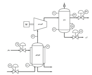
– Definition: P&ID deals with the visualization of piping system components and control and measurement tools and helps in engineering thinking.
– Components:
– Pipes and Connections.
– Valves, sensors and instruments.
– Controllers and other equipment used in the process.
– Application: to identify and name the equipment that needs to be controlled and monitored, as well as to clarify the communication between them.
Sample P&ID
The process and instrumentation diagram is a logical continuation of the flow diagram, because in the latter case, all the necessary information for the construction and operation of the plant is provided. Each specialized engineering unit using an internationally recognized symbology (eg ISA S Series 5) completes or develops parts of its competence by including in this plan:
Equipment data and specifications
Numbering and classification of pipes
Instrumentation in the control room
Instruments and valves available in this field
Construction and installation notes
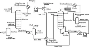
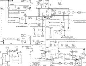
Sample Design of Diagram Done by APIPCO
3. Equipment Process Information
– Definition: includes detailed specifications of each piece of equipment, such as capacity, performance, type of material and other technical characteristics.
– Components:
– Identification number and equipment name.
– Technical specifications and performance (such as temperature, pressure, and capacity).
– Maintenance and repair conditions.
– Application: to ensure the correct selection and use of equipment in the production process.
4. Laboratory Equipment
– Definition: A list of equipment and tools used in tests and product quality control.
– Components:
– Measuring Equipment (such as scales, microscopes and chromatographs).
– Testing Tools (such as non-destructive equipment and resistance testing).
– Application: to check and evaluate the quality of materials, processes and final products.
5. Quality Process Diagrams
– These diagrams deal with the quality control steps in the production process and include quality control criteria and standards.
Process Simulation
By modeling a process, process design engineers can identify flaws and weaknesses in the design and make the necessary corrections. Process optimization is another action that process engineers perform using process simulation.
Process Simulation Steps
simulation is done in two modes.
Steady State simulation
In Steady State simulation, the process is not dependent on time, and in all equations, the changes with respect to time are equal to zero.
Dynamic simulation (Unsteady State)
In the dynamic mode, we first consider the problem conditions as stable and then add the parameters of the dynamic mode to it and finally solve the problem for the dynamic mode. In this case, the software needs more time to perform mathematical calculations.
Most Commonly Used Software in The Process
The following softwares are among the most widely used softwares in the refinery and petrochemical industries.
HYSYS ,Aspen Plus
COMSOL Multiphysics
Aspen B-JAC
aspen HTFS
HTFS ,aspen adsim
Apros
Petrosim
ProMax
PDMS
ProMax

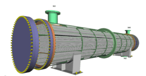
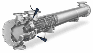
Example of Industrial Simulation Done by APIPCO
Dynamic Simulation of Unit 105 and 107 ASALOUYE in Aspen Plus
Full Simulation of Marjan Pet. Co. Methanol Unit With Aspen Plus
Importance and Applications of PDP
– Guidance for contractors and engineers: PDP provides a key source of information for contractors and engineers to perform their work correctly and according to scientific and industrial standards.
– Project management: Helping project managers in predicting possible problems and challenges and planning for them.
– Reporting and documentation: facilitating the process of reporting to senior managers and stakeholders about project progress and problems.
– Quality assurance: providing a documented basis for guaranteeing the quality of products and equipment, increasing reliability in the production process.
– Clarification of processes: helping to analyze and correctly understand the work flow and equipment performance.
– Identifying critical points: help in identifying points that need more monitoring and control.
– Standardization: creating a standard to evaluate and navigate the production process.
– Improving decision-making: providing the necessary information for better decision-making in product design and development.
The use of these tools and information in the design and development of products can lead to increased quality, reduced costs and improved efficiency.
Conclusion
The process design package is a key tool in engineering and industrial project management. It contributes to the safety, quality and success of the project by providing accurate and comprehensive information about all aspects of a process. This hindsight and attention to detail not only helps improve the performance of industrial projects, but also minimizes potential risks.
