Introduction
The crisis of access to drinking water has become one of the most serious challenges in many parts of the world. Climate change, reduction of water resources and rapid population growth are the factors that have aggravated this problem. According to the United Nations, by 2050, between 2 and 7 billion people may face water shortages.
This issue is especially critical in regions such as the Middle East where fresh water resources are limited. Purifying sea water and using new technologies to sweeten water is an effective solution to deal with these challenges.
The Importance of Water Desalination
Considering that sea water is one of the largest sources of water on earth. It is very necessary to use advanced technologies to turn it into drinkable water. In recent years, several technologies have been developed for seawater purification, each of which has its own advantages and disadvantages. One of the effective and cost-effective methods in this field is membrane distillation or MD.
Introduction to Membrane Distillation (MD)
Membrane Distillation is an innovative method for water desalination. which has several advantages compared to common methods such as reverse osmosis (RO) and thermal distillation. This method converts salt water into fresh water by using special membranes. And DCMD or direct membrane distillation is one of the simplest and most efficient sub-branches of this technology.
In DCMD, salty water at temperatures below its boiling point passes through one side of the membrane, and water vapor moves through the membrane to the other side and then turns into a liquid. This process does not require high pressure and temperature, and these features reduce energy consumption and operating costs.
Also, one of the salient features of DCMD is that solar energy or photothermal energy can be used to power the system, which significantly reduces the overall costs of the process.
Materials Used in DCMD Membranes
Membranes used in DCMD are usually made of synthetic polymers such as polypropylene (PP), polytetrafluoroethylene (PTFE), and polyvinylidene difluoride (PVDF). These materials have high resistance to salt and other pollutants in salt water. Recently, researchers have tried to improve their performance by using graphene oxide on the surface of PTFE and PVDF membranes. The results have shown that these advanced membranes can generate higher permeate flux and also maintain full salt removal capability.
Advantages of Using DCMD
1. Reduction of sedimentation problem: One of the big problems in water desalination systems is sedimentation or fouling. In DCMD, due to the larger pore size of the membrane, this problem occurs less frequently and the fluid passageway is not easily blocked.
2. Lower costs: Due to the need for low pressure and temperature, energy costs in this method are much lower than other sweetening methods.
3. Use of renewable energy: the possibility of using solar or photothermal energy makes this technology a sustainable solution for low consumption areas.
Purpose of The Project
The aim of this project is to develop a comprehensive model that can accurately predict the amount of fresh water produced in the DCMD system. This model also investigates the effect of operating parameters such as temperature, pressure and salt water concentration on the system performance. Using this model, it is possible to achieve optimization of operating conditions and provide. the best solutions to reduce costs and increase the efficiency of water desalination systems.
Laboratory Configuration of DCMD (Direct Membran Distillation) System
The DCMD module consists of a flat membrane and a channel module. This module has two flow chambers made of plexiglass, with the membrane placed between these two chambers. One of these chambers is intended for the flow of hot feed water and the other for the flow of cold permeate water. Water enters through the head and is distributed to three channels, and after passing through the surface of the membrane, the collected liquid is directed to the outlet.
In each flow chamber, there are three rectangular channels with specific dimensions. To improve the permeation flow and prevent internal leakage, a mesh-shaped substitute has been used. A rubber sheet is also used as a gasket. To prevent internal leakage that may occur due to membrane tearing at sharp edges.
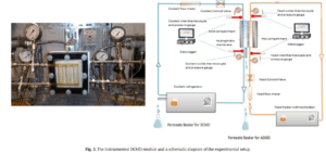
Insulated steel pipes are used to transfer the incoming and outgoing fluids from the heater and cooler. Controlled thermostats provide constant temperatures for the feed and coolant streams. Floating flowmeter is used to measure feed flow and turbine flowmeter is used for cooling flow. Pressure gauges are used to observe the input and output pressure of feed and permeability. and K-type thermocouples are used to monitor inlet and outlet temperatures.
In the experiments, four levels of feed concentrations were tested:
1. Tap water with a concentration of 0.140 grams per liter
2. Aqueous solution of NaCl salt with a concentration of 2 grams per liter
3. Sea water from the Persian Gulf (without pretreatment) with a salt concentration of 43 grams per liter
4. NaCl-water laboratory solution with a concentration of 100 grams per liter
Geometric Modeling Methodology and DCMD System Simulation
In this section, the methodology related to the geometric modeling and governing equations for the DCMD (direct membrane distillation) system according to the paper by Weiming, et al. It is explained. The geometry of the model includes a rectangular flow channel with dimensions of 100 mm length and 2.5 mm height. Computational domain in this model includes feed and permeability channels. The boundary conditions of the system are set as follows:
1.Input of feed and permeation channels are considered as velocity-inlet.
2. Output of the feed and permeation channels is determined as the pressure-outlet.
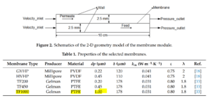
In this simulation, the membrane materials specified in the table above have been used. The membrane module is placed horizontally in the system and NaCl solution is used as feed and pure water as cooling agent. The feed temperature is considered from 45 to 75 degrees Celsius. These values were chosen according to the average temperature of the inlet water, which is about 50 degrees Celsius. The temperature difference of feed and permeation is set from 20 to 50 degrees Celsius. And the flow speed changes in the range of 0.05 to 0.25 m/s.
DCMD System Simulation in Comsol Software
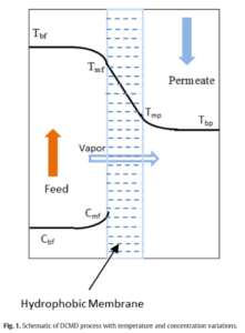
In this project, the main goal was to investigate and optimize the performance of a DCMD module through detailed simulations in COMSOL Multiphysics software. The desired module consists of a hydrophobic membrane on which the flow of hot salty water passes from one side and the flow of cold fresh water from the other side. The temperature difference between the two sides of the membrane causes a difference in vapor pressure. which causes the transfer of water vapor from the hot side to the cold side. And finally, the distilled water is collected.
In this project, after the initial simulation of momentum and heat, the focus is on adding mass balance and reaction equations to the model. This work has included adding new physics to the system, defining variables and parameters, and setting boundary conditions for a more accurate simulation of the mass and heat transfer process. The equations related to mass and heat transfer have been carefully entered in the software and the necessary optimizations have been made.
This report includes detailed explanations of the modeling process, introduction of the equations used, and analysis of the results obtained from the simulations. The aim of this project is to provide a comprehensive and practical model to predict and improve DCMD system performance, as well as to provide insights into the effect of various operational parameters on system behavior and freshwater production rates.
Final Physics Used
Mass and heat transfer modules have been added to the COMSOL software and the variables and parameters of the problem have been completed. For modeling, from the equations and relationships in the article of A. Khalifa et al. It has been provided, it has been exploited. In this project, the geometry and general conditions are considered as follows:
The system includes a DCMD module. that the hot flow of salt water (feed) passes through one side of the hydrophobic membrane and the cold flow of fresh water (permeable) is on the other side of the membrane. The temperature difference between the two sides of the membrane creates a vapor pressure difference, which directs water vapor from the hot feed side to the cold permeate side. After passing through the pores of the membrane, the water vapor is distilled on the cold permeation side and turns into a liquid state.
Adding Equations to The System
At first, mass transfer modules are added to COMSOL and desired domains are assigned to each of these modules. Then materials and components, including water and NaCl salt, are added to the system.
Mass Transfer Equations
The following equation is used to calculate the mass transfer flux:

We add the current pressure of the material in the above equation from the following formula:
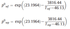
The considered activity coefficient is obtained from the following formula:

The overall penetration coefficient is obtained from the following formula:

where alpha is a number between 0 and 1. We considered 0.7 to create the Knudsen infiltration bed. The rest of the parameters are obtained from the following formulas:
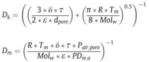
In the above formula, PDwa is obtained from the following relations:
![]()
where Tm is the average temperature of the membrane surfaces in the hot and cold parts of the module. The above information was entered in the software and the exact formulas were coded in the system. The modules are also coupled with physics.
Heat Transfer Equations
For heat transfer, boundary conditions and modeling assumptions in the system are fully added. Displacement heat transfer using Newton’s law is written as follows:
![]()
The heat transfer in the membrane structure itself, which is a function of the mass transfer of the system, is entered into the Comsol with the help of the following relationship:
![]()
that the enthalpy changes in the above relationship alone is a function of other parameters. The enthalpy equation is obtained from the following formula:
![]()
Here, Tmf is the mean surface temperature of the membrane in the hot and cold part of the module. After solving the momentum and heat equations, by averaging the temperature parameter around the desired locations, the numerical value of this parameter was determined and entered in the COMSOL parameters section.
For conductive mass transfer (not displacement) in a membrane, Fourier law is entered into COMSOL as follows:

In the above relationship, km is an unknown parameter. This parameter is calculated for each porous material from the following equation:

In heat transfer, sometimes auxiliary equations are also solved. In the article, some auxiliary equations have been added to the system, which we use if necessary.
Boundary Conditions
In this section, mass transfer parameters are entered and boundary conditions are displayed to the system. It should be noted that the boundary condition in the hot section should be shown to the software as the coupled concentration in the membrane.
Simulation Results
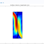
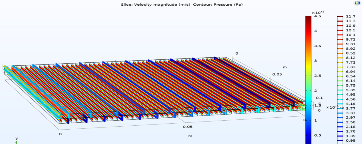
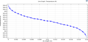
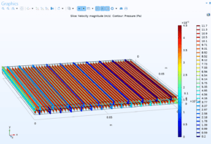
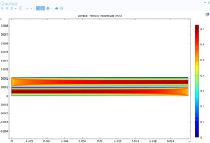
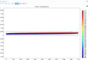
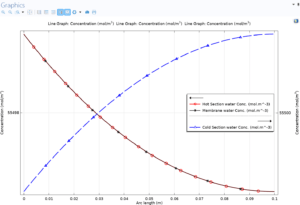
To complete the hydraulic results of the membrane, the temperature diagram inside and outside the membrane is drawn. The figures below show the temperature diagram inside the membrane from the hot fluid side to the cold fluid side, the three-dimensional view of the modeled module. By displaying velocity and pressure, it displays velocity contour, temperature profile and concentration profile.
3D View of The Modeled Module With SSpeed and Pressure Display:
Speed Contour:
Temperature Profile:
Concentration Profile:
Modeling and Simulation of DCMD Membrane Distillation Module
In this project, the modeling and simulation of the direct contact membrane distillation (DCMD) module has been done using COMSOL software. This project comes with full training.
