
Introduction
With the rapid growth of the global population and the increasing demand for energy, the use of renewable energy sources has become more important than ever. Due to the environmental consequences of fossil fuels, we are seeking clean and sustainable solutions. Wind energy, as one of the clean and inexhaustible resources, has gained a special place in this transition. The use of wind energy helps reduce greenhouse gas emissions and enhances the efficiency of energy systems. The CCHP System is an effective approach to minimizing energy losses during transmission and end-use consumption. These systems integrate multiple thermodynamic cycles to simultaneously produce electricity, heating, and cooling, thereby reducing costs and improving efficiency.
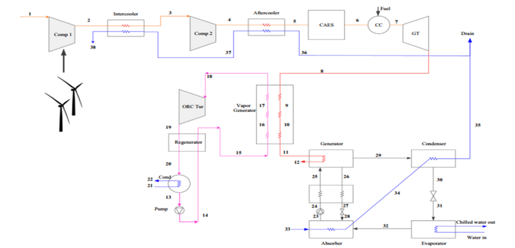
In this project, we designed an integrated system that meets electrical, heating, and cooling needs simultaneously with minimal energy loss. Our system consists of two main components:
Primary Cycle (Compressor – Storage – Gas Turbine):
- Ambient air is compressed by two compressors. The energy required for the compressors is supplied by a wind turbine.
- The compressed air passes through heat exchangers, which reduce the energy required for the compressors and produce hot water.
- The compressed air is transferred to a storage tank (CAES). When needed, the stored air is used to generate electricity or heat.
Secondary Cycles:
- Organic Rankine Cycle (ORC):
The residual energy in the exhaust gases from the gas turbine is converted into steam, which is then used by the Organic Rankine Cycle turbine to generate electrical energy. - Ammonia-Water Cooling Cycle:
The excess energy in the exhaust gases is recovered and used to produce cooling for residential and commercial spaces.
This integrated CCHP System, utilizing advanced renewable energy technologies and combining multiple thermodynamic cycles, is a practical example of sustainable and optimized energy supply. The precise design of components, comprehensive modeling, and detailed analysis enable optimal utilization of energy resources, making it a significant contributor to sustainable energy development on small and medium scales.
System Description
In the integrated CCHP system, the diagrams below examine the impact of the maximum pressure in the compressed air storage tank. The following sections provide a detailed explanation of the effects of this parameter and the related diagrams:
Increasing Storage Tank Pressure (Maximum Pressure of Air Cavern)
Increased Compressor Work:
Higher pressure requirements in the tank mean that compressors must compress ambient air to a higher pressure, consuming more energy in the process.

Higher Compressor Outlet Temperature:
Increased pressure leads to a higher outlet temperature of the compressed air, which can be beneficial for producing hotter water if that is a primary goal of the system.

Longer Charging and Discharging Times:
Higher pressure increases the density of the air entering the tank, resulting in longer times for both charging and discharging the tank.
Net Energy Production:
While longer discharging times increase net energy production over a given period, longer charging times also increase energy consumption, leaving the ratio of energy produced to energy consumed relatively unchanged.

Hot Water Production:
Higher pressure aids in increasing the outlet temperature of the compressors, which is advantageous if the primary goal is to produce hot water.

Minimum Storage Tank Pressure (Minimum Pressure of Air Cavern)
Reduced Charging and Discharging Times:
Increasing the minimum pressure reduces the time required for both charging and discharging the tank.
Energy Input and Output:
Shorter charging times reduce the energy input to the system, while shorter discharging times reduce the energy output, resulting in a mild overall impact on system performance.


Mass Flow Rate of Air Exiting the Tank
Increased Gas Turbine Output:
A higher mass flow rate of air exiting the tank directly increases the work output of the gas turbine.

Reduced Discharging Time:
Increased flow rates reduce the discharging time, leading to higher power output but shorter operational periods for the turbine.


Gas Turbine Inlet Temperature
Increased Turbine Work:
Higher inlet temperatures increase the energy input to the turbine, leading to higher output temperatures.

Enhanced Heat Transfer:
Higher outlet temperatures increase the heat transfer to the cooling cycle, boosting cooling capacity and energy input to the combustion chamber.

Organic Rankine Cycle (ORC)
Increased Turbine Work:
Higher inlet temperatures to the ORC turbine increase its work output but reduce the energy available for the cooling cycle, decreasing cooling capacity.
")
Increased Inlet Pressure:
Higher inlet pressures in the ORC turbine similarly affect its performance, though not as significantly as temperature changes.


Cooling Cycle Pressure
Increased Cooling Capacity:
Higher minimum pressure in the cooling cycle increases its cooling capacity.

Reduced Cooling Capacity:
Higher maximum pressure in the cooling cycle reduces its cooling capacity and slightly increases exergy loss.


Heat Exchanger in the Cooling Cycle
Improved Heat Transfer:
Optimal performance of the heat exchanger in the cooling cycle enhances heat transfer, improving the efficiency of the absorption cycle and overall system performance.

Key Parameter Analysis
Storage Tank Charging Pressure (Maximum Pressure of Air Cavern):
-
- Increased Pressure: Higher pressure increases compressor work and outlet temperature, beneficial for hot water production but also increases energy consumption.
- Charging and Discharging Times: Higher pressure increases charging and discharging times, affecting net energy production.
Storage Tank Discharging Pressure (Minimum Pressure of Air Cavern):
-
- Reduced Charging and Discharging Times: Higher minimum pressure reduces charging and discharging times, with a mild impact on overall system performance.
Tank Temperature:
-
- Impact on Charging and Discharging Times: Temperature changes have little effect on charging and discharging times.
- Useful Energy Production: Higher temperatures reduce fuel requirements and improve energy production efficiency.
Mass Flow Rate of Air Entering the Tank:
-
- Increased Flow Rate: Higher flow rates increase energy consumption but reduce compressor operation time, enhancing hot water production.
Mass Flow Rate of Air Exiting the Tank:
-
- Increased Turbine Output: Higher flow rates increase turbine output but reduce operational periods, impacting overall system efficiency.
Important Modeling Considerations
- Flue Gas Flow: Due to limitations in simulating the exact gas composition, carbon dioxide properties were used in REFPROP software.
- ORC Turbine Modeling: An isentropic assumption was made for the ORC turbine, with actual enthalpy values derived using isentropic efficiency.
- Parameter Sensitivity Analysis: Key parameters were held constant during sensitivity analysis to isolate their effects.
- Pressure Loss in Transfer Paths: Pressure losses in pipelines were not considered, as they have minimal impact on system output.
Related Projects
Simulation of Combined Cycle (CHP, CCHP for Power Generation) with Aspen Plus
Conclusion
This report analyzed an integrated CCHP system based on wind energy and compressed air energy storage (CAES). The results indicate that optimizing parameters such as tank pressure, air mass flow rates, and operational temperatures can lead to high energy efficiency, reduced exergy losses, and simultaneous production of electricity, heating, and cooling. Increasing tank pressure enhances hot water production, improves energy efficiency, and reduces the need for fossil fuels. Sensitivity analysis of key parameters shows that precise adjustments can optimize system performance under various operational conditions. SANILCO, as a leader in innovative renewable energy solutions, plays a crucial role in enhancing energy efficiency and reducing environmental impacts through the design and development of advanced CCHP systems utilizing modern technologies like wind energy and CAES. This project exemplifies SANILCO’s commitment to sustainable and efficient energy solutions, contributing to global carbon reduction goals and improved energy system efficiency.